
This guide takes a Cisco Catalyst L3 switch from "Access Gate in the rack" to "OT traffic flowing through the gate," end to end. You connect two ports, give the gate a place on the network, and choose how traffic reaches it. Nothing on the OT devices changes.
What you will build
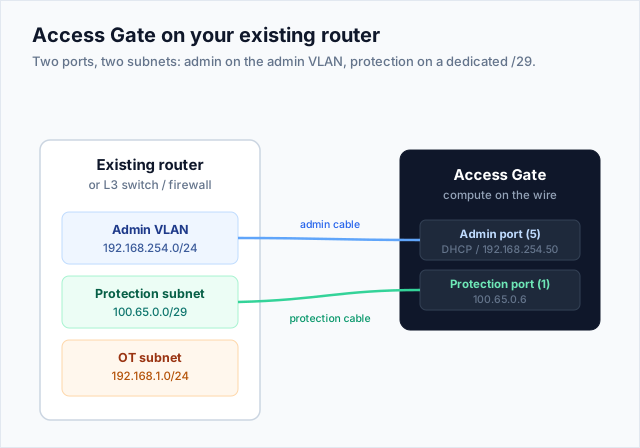
The Access Gate is a physical appliance you cable to two switch ports on two different subnets: an admin port on your admin VLAN, and a protection port on a small dedicated subnet that carries the traffic you steer through the gate.
Reference lab
| Element | Address | Role |
|---|---|---|
| Admin VLAN | 192.168.254.0/24 | Where the Access Gate web console is reached |
| Access Gate admin port (5) | DHCP, or 192.168.254.50 | Management interface |
| Protection subnet | 100.65.0.0/29, switch 100.65.0.1 | Point-to-point link to the gate |
| Access Gate protection port (1) | 100.65.0.6 | Traffic in/out, overlay, and DNS resolver |
| Secure Twin overlay | 100.64.0.0/16 | Parallel space; each asset gets a 1:1 twin |
| OT subnet | 192.168.1.0/24, PLC 192.168.1.10 (twin 100.64.1.10) | Assets, unchanged |
| DNS zone | secure.acme.corp, resolver 100.65.0.6 | Names for assets |
1. Physical connectivity: two ports, two subnets
Put the admin port and the protection port on different subnets so management traffic and steered traffic never share a broadcast domain. The admin VLAN is your existing management network; the protection subnet is a dedicated /29.
! Admin VLAN (management) and a dedicated protection subnet
vlan 254
 name ADMIN
vlan 65
 name AG-PROTECT
!
interface Vlan254
 ip address 192.168.254.1 255.255.255.0
interface Vlan65
 ip address 100.65.0.1 255.255.255.248
!
! Access Gate admin port  -> switchport in the admin VLAN
interface GigabitEthernet1/0/5
 description Access-Gate-ADMIN (port 5)
 switchport mode access
 switchport access vlan 254
!
! Access Gate protection port -> switchport in the protection VLAN
interface GigabitEthernet1/0/1
 description Access-Gate-PROTECT (port 1)
 switchport mode access
 switchport access vlan 65
Cable Gi1/0/5 to the Access Gate admin port (5) and Gi1/0/1 to the protection port (1). The admin interface takes a DHCP lease from the admin VLAN, or defaults to 10.0.0.1 after about a minute if there is none; set it static to 192.168.254.50 from the console if you prefer a fixed address.
2. Give the overlay a route
The Secure Twin lives in the 100.64.0.0/16 overlay, the parallel address space where every asset gets a twin. Add one static route so that any traffic destined for that range is forwarded via 100.65.0.6, the Access Gate's protection port:
ip route 100.64.0.0 255.255.0.0 100.65.0.6
Read it as: for the destination network 100.64.0.0/16, send the packet to 100.65.0.6. From here on, anything addressed to a twin (overlay) address leaves the switch, arrives at the Access Gate on its protection port, and the gate proxies it to the real device, so reaching a twin address is what pulls the flow through the gate.
3. Point DNS at the Access Gate
The gate hosts a resolver at 100.65.0.6 that turns asset names into overlay addresses. You can use it for everything or only for a subdomain.
-
Everything: hand the resolver to clients over DHCP:
ip dhcp pool OT network 192.168.1.0 255.255.255.0 default-router 192.168.1.1 dns-server 100.65.0.6 -
Subdomain only: keep your existing DNS and forward just
secure.acme.corpto the gate with a conditional forwarder on your site DNS server (Windows DNS, BIND, or Infoblox). See Configuring Access Gate DNS for the split-DNS pattern.
4. Steer traffic through the gate
Two ways to get traffic to the gate. Source-based secures what comes from a network: you match on where the packet started. Destination-based secures what goes to an asset: you match on where it is headed. Use one, the other, or both, depending on what you want to protect. Either way the Access Gate translates between the asset's real address and its twin.
Source-based: securing what comes from the OT subnet
ip access-list extended OT-TRAFFIC
 permit ip 192.168.1.0 0.0.0.255 any
!
route-map STEER-OT permit 10
 match ip address OT-TRAFFIC
 set ip next-hop 100.65.0.6
!
interface Vlan1
 description OT SVI
 ip policy route-map STEER-OT
Every packet leaving the OT subnet goes to the gate, whatever its destination. One rule brings the whole subnet under the Secure Twin without touching a device. This is the Catalyst form of source-based routing.
Destination-based: securing what goes to an asset
! The overlay route from step 2 already covers every twin
ip route 100.64.0.0 255.255.0.0 100.65.0.6
!
! Or just one asset
ip route 100.64.1.10 255.255.255.255 100.65.0.6
Anything addressed to a twin goes to the gate, whoever sent it. No PBR needed, it is ordinary destination routing. See gateway NAT (L3).
5. Verify the full path
From an OT device, reach a destination exactly as before. The switch now steers the flow through the gate on the way out.
ping 192.168.2.20 ! from the OT device (192.168.1.10)
On the Access Gate, the flow appears under its enclave with the device's overlay identity (100.64.1.10); identity, policy, and encryption apply before the packet is forwarded, and the reply is NATed back to the real device.
You can also test the IT to OT direction: from an IT client, reach an OT asset by its twin address or DNS name (ping 100.64.1.10). The overlay route carries that packet to the gate, which proxies it to the real device.
What lives where
The Catalyst holds one thing: a rule that says, in effect, "these packets, hand them to this next hop." It is static. You write it once and never touch it again, even as enclave policy changes from week to week.
Everything else lives on the Access Gate: authentication, the enclave ACLs, proxying, credential injection, session recording, TLS termination, and logging. None of that is expressible on a Catalyst 9300, and none of it goes there.
That separation is worth saying out loud to the network team, because "we need to configure your core switch" sounds alarming until they see it is a handoff rule, not a policy engine. Their change control sees a route-map, once.
Recap
You cabled two Catalyst ports on two subnets (admin VLAN + protection /29), addressed the gate at 100.65.0.6, routed the overlay to it, pointed DNS at its resolver, and steered traffic by source, by destination, or both. OT traffic now flows through the Access Gate with no change to any asset.